Shenzhen Wandanan Precision Technology Co., Ltd Info@szwandaancnc.com


Views: 0 Author: Site Editor Publish Time: 2026-08-18 Origin: Site


Electronic component failure frequently stems from inadequate environmental protection, poor thermal management, or mechanical stress. These physical issues tie directly back to the initial enclosure design. Relying on off-the-shelf enclosures forces severe engineering compromises. You end up with suboptimal PCB layouts, restricted I/O placement, and inadequate EMI shielding. These forced compromises delay time-to-market and increase field failure rates when devices face real-world conditions. To prevent late-stage redesigns, engineering teams must adopt a concurrent ECAD/MCAD co-design approach. This methodology bridges the gap between PCB layout requirements and mechanical constraints. Transitioning to a custom metal chassis requires rigorous evaluation. You must analyze material science, Design for Manufacturability (DFM), and regulatory compliance. This technical framework provides the exact parameters needed to design, engineer, and source custom enclosures effectively without relying on generic boxes.
Material selection and thickness dictate the baseline performance of the chassis, requiring a calculated trade-off between thermal dissipation, EMI shielding, weight, and unit cost.
Strict adherence to sheet metal DFM principles—specifically regarding bend radii, hole clearances, and fastener integration—is non-negotiable for controlling manufacturing costs and lead times.
Environmental compliance (IP/NEMA ratings), electromagnetic compatibility (EMC), and electrical grounding must be engineered into the structural design early, not applied as post-production fixes.
Evaluating and integrating a precision metal parts manufacturer during the prototyping phase significantly reduces scaling risks and tooling revisions during high-volume production.
Standardized enclosures impose severe physical constraints on product design. They dictate PCB geometry, component height limits, and connector placements. Engineers often alter ideal board layouts just to fit pre-existing mounting bosses. This forces dense component grouping. Dense grouping exacerbates heat generation and creates localized hot spots on the board. Standard units also feature unoptimized ventilation patterns. Generic cutouts rarely align with your specific heat-generating components like microprocessors or power supplies. This misalignment creates thermal bottlenecks that degrade component lifespan. Moving away from a generic electronic enclosure eliminates these forced compromises. You gain complete control over internal volume allocation. You can place heavy transformers directly over structural supports and route cables without pinching them against generic internal ribs.
Establishing clear baseline requirements ensures the final design meets operational demands. You must define mechanical rigidity and shock resistance based on the deployment environment. Industrial settings require higher vibration tolerance than office environments. Spatial constraints dictate the outer dimensions and mounting style.
Mounting Configuration: Specify whether the unit requires 19-inch rack-mount ears, 35mm DIN rail clips, or standalone rubber feet.
Vibration Isolation: Determine if internal components need floating mounts or rubber dampeners to survive transit or operational shaking.
Cable Management: Plan exact routing paths, tie-down points, and strain relief locations for all internal wiring harnesses.
I/O Accessibility: Map out exactly where users need to plug in cables, ensuring adequate finger clearance around each port.
Aesthetic and branding expectations also drive design choices. Custom designs allow for integrated logos, specific color matching, and unique form factors. Defining these parameters early streamlines the engineering process for custom hardware parts.
Evaluate how often technicians or users will access the internal components. Permanently sealed units work well for disposable or zero-maintenance devices. Complex electronics require accessible entry points. Incorporate removable access panels for quick component swapping. Use captive screws to prevent hardware loss during field repairs. Dropping a standard machine screw into a live power supply causes catastrophic shorts. Captive hardware stays attached to the panel. Hinged doors provide rapid access without requiring tools. Design these access points to maintain environmental seals and EMI shielding when closed. Specify compressible conductive gaskets around door perimeters. Proper serviceability reduces downtime and lowers maintenance labor over the product lifecycle.
Sheet metal thickness directly impacts structural strength, overall weight, and material cost. Thicker gauges provide superior rigidity for heavy internal components. However, they increase unit weight and complicate the bending process. Thinner gauges reduce costs and weight but require structural reinforcements like ribs, hems, or flanges to prevent oil-canning or warping. Select a gauge that balances these factors. Consider the mounting method and expected physical abuse when specifying thickness. Standardize the gauge across the entire assembly where possible. Using a single material thickness means the press brake operator does not need to change tooling between parts. This reduces setup time and lowers your per-unit cost.
| Gauge (Steel) | Thickness (Inches) | Thickness (mm) | Typical Application |
|---|---|---|---|
| 14 Gauge | 0.075 | 1.90 | Heavy-duty industrial chassis, transformer mounts |
| 16 Gauge | 0.060 | 1.52 | Standard rack-mount equipment, structural panels |
| 18 Gauge | 0.048 | 1.21 | Desktop enclosures, internal brackets |
| 20 Gauge | 0.036 | 0.91 | Lightweight handheld devices, cosmetic covers |
Aluminum dominates electronic enclosure design due to its high strength-to-weight ratio. Alloys like 5052-H32 and 6061-T6 offer natural corrosion resistance without additional coatings. An aluminum chassis enclosure provides superior thermal conductivity. This allows the enclosure itself to act as a massive heat sink. You can mount hot components directly to the chassis wall using thermal paste. Aluminum is highly machinable and easy to bend. It does not spring back as aggressively as stainless steel during forming. This reduces tooling wear and accelerates fabrication times. Its lightweight nature significantly lowers shipping costs for high-volume production runs.
Cold Rolled Steel (CRS) offers exceptional structural advantages for heavy-duty applications. It provides high tensile strength at a lower raw material cost than aluminum. CRS requires surface finishing, like powder coating or plating, to prevent rust. This adds a manufacturing step and increases lead time. Stainless steel, specifically grades 304 and 316, excels in harsh environments. It delivers maximum corrosion resistance and meets strict hygiene standards for medical or food-grade applications. Harder metals introduce inherent weight penalties. They also cause faster tooling wear on punches and dies. Bending stainless steel requires higher tonnage press brakes and careful calculation of spring-back angles.
Galvanneal provides a practical alternative to stainless steel for rust prevention. It consists of carbon steel coated with a zinc-iron alloy through a continuous hot-dip process. This coating offers excellent paint adhesion and moderate corrosion resistance. It eliminates the need for aggressive surface preparation before powder coating. For extreme requirements, consider specialty copper alloys. Copper provides unmatched electrical grounding, conductivity, and thermal transfer. Due to high material costs and heavy weight, engineers typically reserve copper for specific internal shielding components or busbars rather than entire exterior enclosures.
| Material | Strength-to-Weight | Thermal Conductivity | Corrosion Resistance | Relative Cost |
|---|---|---|---|---|
| Aluminum (5052) | High | Excellent | High (Natural) | Moderate |
| Cold Rolled Steel (CRS) | Moderate | Low | Poor (Needs Finish) | Low |
| Stainless Steel (304/316) | Moderate | Low | Excellent | High |
| Galvanneal | Moderate | Low | Good | Low-Moderate |
The relationship between material thickness and minimum bend radius dictates forming success. Forcing a tight radius on thick material causes micro-fracturing along the outside of the bend line. This weakens the structure and creates cosmetic defects that show through powder coat. Always specify a bend radius equal to or greater than the material thickness. Bend relief notches are equally necessary. These small cutouts prevent material tearing where two bends intersect at a corner. Functional flat surfaces for mounting components do not begin until clear of the bend radius and the die mark zone. Account for this transition zone when placing internal standoffs. If you place a standoff too close to the radius, the hardware will sit at an angle, putting stress on the PCB.
Placing holes too close to a bend line causes severe material distortion during forming. The press brake die pulls the metal, stretching any nearby holes into ovals. Maintain a minimum distance of 1.5 times the material thickness plus the bend radius from the edge of the hole to the bend line. This rule applies to all cutouts, louvers, and edges. For fastening, evaluate self-clinching hardware like PEM nuts, studs, and standoffs. They provide strong, reusable threads in thin sheet metal. Tapped holes require thicker materials to hold adequate thread engagement. Using self-clinching fasteners in a metal chassis streamlines assembly. It eliminates the need for workers to fumble with loose nuts and washers during final integration.
Safe, conductive pathways are mandatory for electronic enclosures to prevent shock hazards and ensure signal integrity. Plan the strategic placement of grounding studs during the CAD phase. These studs must connect directly to bare metal to function properly. If you plan to paint or powder coat the chassis, you must specify masking areas on your drawings. Masking prevents insulating finishes from covering grounding points. Consider using clear chem-film (chromate conversion) on aluminum parts. This finish maintains electrical conductivity across the entire surface while providing a baseline level of corrosion resistance. It eliminates the labor-intensive process of applying and removing masking tape.
Seam welding provides exceptional structural integrity and permanent environmental sealing. It fuses the corners into a single continuous piece of metal. However, welding incurs high labor costs and introduces heat distortion risks, especially on thin aluminum. Grinding welds smooth for cosmetic appearance adds further manual labor. Mechanical fastening and riveting offer scalable, cost-effective alternatives. Rivets provide permanent, vibration-resistant joints without heat distortion. Machine screws allow for modular designs and easy disassembly for end-of-life recycling. Choose fastening methods based on production volume, sealing requirements, and the need for future maintenance access.
| Assembly Method | Structural Integrity | Environmental Sealing | Labor Cost | Disassembly |
|---|---|---|---|---|
| Seam Welding | Excellent | Excellent (Permanent) | High | Impossible |
| Spot Welding | Good | Poor (Gaps exist) | Moderate | Impossible |
| Riveting | Good | Moderate | Low | Difficult (Requires drilling) |
| Machine Screws | Moderate | Depends on gaskets | Low | Easy |
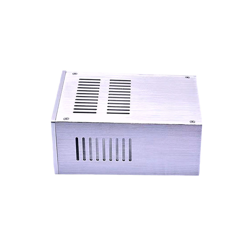
Effective cooling requires strategic ventilation design. Hexagonal hole patterns maximize open airflow area while maintaining structural rigidity better than round holes. Align these ventilation zones directly with internal heat sources. Design the chassis to function as a primary heat sink. Integrate thermal pads between hot components and the metal casing. Place standoffs strategically to ensure adequate airflow underneath the PCB. For active cooling, design secure fan mounts with integrated finger guards. Punching the finger guard directly into the sheet metal reduces your overall part count and assembly time. Ensure the exhaust area is at least 1.5 times larger than the intake area to prevent positive pressure buildup, which stalls fan blades.
Metal enclosures inherently provide excellent Faraday cage properties. Seams, ventilation cutouts, and display windows create vulnerabilities for EMI leakage. Mitigate these risks by designing overlapping joints at all enclosure seams. A simple butt joint allows high-frequency waves to escape. An overlapping flange forces the waves through a labyrinth, degrading their energy. Use conductive gaskets to seal gaps between mating panels. Minimize the length of any necessary slots or cutouts. A slot acts as an antenna if its length approaches one-quarter of the target electromagnetic wavelength. Break long slots into smaller, segmented cutouts to block specific high-frequency emissions.
Achieving specific ingress protection ratings requires structural foresight. IP65 or NEMA 4 ratings demand complete protection against dust and low-pressure water jets. Design overlapping flanges to direct water away from internal seams using gravity. Incorporate labyrinth seals to create complex paths that trap moisture before it enters the main cavity. Specify compressible closed-cell sponge gaskets for all access panels and doors. Ensure the fastening system provides uniform compression across the entire gasket surface. Place screws no more than three inches apart along the gasket line. Uneven pressure creates microscopic gaps that compromise the environmental seal during temperature cycling.
| IP Rating | Protection Level | Design Requirement |
|---|---|---|
| IP20 | Fingers and large objects | Standard cutouts, no special sealing required. |
| IP54 | Dust protected, splashing water | Overlapping seams, basic foam gaskets. |
| IP65 | Dust tight, water jets | Continuous closed-cell gaskets, labyrinth seals, tight screw spacing. |
| IP67 | Dust tight, temporary immersion | Welded seams, O-rings, potted cable glands, heavy-duty latches. |
Surface finishes protect the metal and define the product's visual identity. Anodizing increases surface hardness and corrosion resistance for aluminum parts. It penetrates the metal, preventing chipping or peeling. Powder coating offers extreme durability and a wide color palette. It resists scratches better than traditional wet paint and emits zero VOCs during application. Chem-film provides corrosion resistance while maintaining electrical conductivity. Masking specific areas during powder coating ensures bare metal contact for EMI grounding. This trade-off requires precise documentation. You must provide clear 2D drawings indicating exact masking zones to avoid manufacturing errors on the paint line.
Permanent labeling enhances usability and safety. Incorporate silkscreening for high-contrast I/O port identification and corporate branding. Digital printing allows for complex, multi-color graphics directly on the metal surface. For harsh environments, specify laser engraving. Engraving removes the top layer of finish, exposing the bare metal underneath. This creates permanent safety warnings, grounding symbols, and serial numbers that cannot wear off, peel, or fade over time. Integrate these aesthetic choices into the initial design files rather than treating them as an afterthought.
Your manufacturing partner must integrate seamlessly with your engineering workflow. Ensure they accept standard 3D CAD files like STEP or IGES. A capable precision metal parts manufacturer provides mechanical-mindset feedback on your designs. They identify PCB layout constraints that clash with sheet metal realities, such as components placed too close to a bend radius. This co-design capability catches interference issues before tooling begins. Early collaboration prevents costly redesigns and accelerates the transition from virtual model to physical prototype.
Evaluate how the manufacturer handles scaling. Low-volume fabrication relies on laser cutting and manual press brakes. This method offers high flexibility and low setup costs, perfect for iterative prototyping. High-volume production requires hard tooling and progressive die stamping. This drastically reduces unit costs but requires significant upfront investment in steel dies. Understand the manufacturer's equipment limits. Maximum press brake tonnage and bed size dictate the maximum dimensions and thickness they can process. Ensure their capabilities align with your projected production volumes so you do not have to switch vendors mid-lifecycle.
Strict quality control guarantees assembly success. Verify the manufacturer holds relevant ISO certifications, such as ISO 9001 for general manufacturing or AS9100 for aerospace applications. Review their process for generating First Article Inspection (FAI) reports. FAI reports verify that the initial production run meets all CAD specifications before full production begins. Establish acceptable tolerance stacks for complex assemblies early in the relationship. Standard sheet metal tolerances are looser than machined parts. Tight tolerances increase costs, so only specify them where critical for fit or function, such as around connector cutouts or mating seams.
Finalize your 3D CAD models with integrated PCB layouts to identify spatial conflicts and thermal bottlenecks before cutting metal.
Define exact environmental compliance targets, including IP or NEMA ratings, to dictate flange design and gasket selection.
Initiate a comprehensive DFM review with a vetted manufacturing partner to optimize bend radii, hole placements, and hardware insertion.
Establish clear masking and finishing requirements on 2D drawings to ensure proper electrical grounding and EMI shielding.
A: Standard sheet metal fabrication tolerances typically range from ±0.005 to ±0.015 inches. Tighter tolerances are achievable but require specialized machining or hard tooling, which increases production costs. Always specify tolerances based on functional necessity rather than default CAD settings to control manufacturing expenses.
A: Select thickness based on structural load, weight limits, and mounting requirements. Heavy internal components require thicker gauges, like 14 or 16-gauge steel, to prevent flexing. Handheld or lightweight devices benefit from thinner materials, such as 18 or 20-gauge aluminum, to reduce overall weight and material costs.
A: Choose aluminum for lightweight applications, superior thermal conductivity, and ease of machining. It fits most commercial electronics perfectly. Choose stainless steel for harsh environments requiring maximum corrosion resistance, high tensile strength, or strict hygiene compliance, such as medical devices or marine equipment.
A: Powder coating is generally the most cost-effective and durable finish for steel and aluminum enclosures. It provides a thick, scratch-resistant layer. For aluminum parts requiring electrical conductivity, clear chem-film (chromate conversion) is highly cost-effective while offering a baseline level of corrosion protection.
A: The minimum bend radius dictates how tight a corner can be formed without cracking the metal. It should equal or exceed the material thickness. You cannot place functional features, such as mounting holes or cutouts, within this radius zone without causing severe material distortion during the bending process.
A: Yes. Metal naturally reflects and absorbs electromagnetic interference, acting as a Faraday cage. Plastic enclosures offer zero inherent EMI shielding and require expensive conductive coatings or internal metal foils to achieve compliance. Custom metal designs allow for engineered overlapping seams to maximize this shielding effect.


