Shenzhen Wandanan Precision Technology Co., Ltd Info@szwandaancnc.com


Views: 0 Author: Site Editor Publish Time: 2026-08-28 Origin: Site


As electronic components achieve unprecedented power densities—from EV inverters to high-performance computing—standard off-the-shelf thermal solutions routinely fail to meet stringent temperature and spatial constraints. Identifying the exact inflection point where unique form factors, extreme heat flux, or proprietary board layouts mandate a move away from standard catalogs to a bespoke thermal solution separates successful product launches from field failures. Specifying a custom unit is rarely a simple geometry exercise. It requires balancing thermal resistance targets, pressure drop limits, manufacturability, and unit economics at scale. To successfully navigate custom heat sink manufacturing, engineers must align their thermal management requirements with the correct fabrication processes, material properties, and a rigorously vetted heat sink manufacturer capable of bridging the gap between CFD simulation and high-volume production.
Fabrication dictates feasibility: The choice between extrusion, skiving, and CNC machining strictly governs achievable fin aspect ratios, tooling costs, and production lead times.
Material selection involves trade-offs: While copper offers superior thermal conductivity, custom aluminum heat sinks dominate due to optimal ratios of thermal performance to weight, cost, and machinability.
Prototyping risks require mitigation: Validating thermal models with a prototype made via a different process than the final production run (e.g., machining vs. die casting) introduces critical performance discrepancies.
Vendor compliance is non-negotiable: Mission-critical applications require manufacturers with verifiable AS9100D, IATF 16949, or ISO 9001:2015 certifications and in-house metrology.
Effective thermal management starts with rigid performance baselines. You cannot design a thermal solution based on physical dimensions alone. The physics of heat transfer must dictate the geometry. Engineers must establish clear metrics before selecting a manufacturing process, ensuring the final product performs reliably under peak loads.
Establish hard targets for junction-to-ambient (θJA) and case-to-sink (θCS) thermal resistance early in the design phase. These metrics define exactly how efficiently heat moves from the silicon die through the packaging, into the heat sink, and finally into the surrounding air. You must calculate the maximum allowable thermal resistance based on the maximum ambient operating temperature and the component's maximum junction temperature. Failing to account for worst-case ambient conditions leads to thermal throttling.
Determine the airflow regime next. Passive natural convection requires widely spaced fins to allow buoyancy-driven air to flow without excessive boundary layer interference. Forced convection allows for much denser fin arrays. Choose straight, flared, or omnidirectional pin fins based on the system's specific airflow path. Flared fins help reduce bypass airflow in un-ducted environments. Pin fins provide excellent performance when airflow direction is unpredictable or multi-directional, breaking up boundary layers effectively.
Define the maximum allowable pressure drop for forced convection systems. Pushing air through a dense fin array creates resistance. Exceeding the pressure drop limit causes the fan or blower to stall, drastically reducing airflow and causing rapid overheating. Map strict volumetric constraints carefully. Note Z-height limits, overall footprint restrictions, and board keep-out zones. Consider the entire assembly envelope, including the space required for airflow ingress and egress, as well as cable routing paths.
Determine shock and vibration tolerances. This is critical for aerospace, railway, and automotive applications. A heavy copper heat sink mounted only by the component leads will shear off under high vibration. Specify integrated mounting hardware requirements upfront. Press-fit pins, spring clips, and threaded inserts reduce secondary assembly steps on the production line. They also ensure consistent mounting pressure across the thermal interface, which is vital for maintaining a thin bond line.
Specify weight budgets clearly. Weight impacts structural integrity and shipping logistics. Identify necessary surface treatments based on the operating environment. Type II or Type III anodizing improves thermal emissivity for radiation and protects against harsh environmental corrosion. Nickel plating allows for direct soldering to PCBs. Chromate conversion maintains electrical conductivity for grounding purposes while offering mild corrosion resistance. Bare aluminum oxidizes rapidly, creating a resistive layer that impedes thermal transfer at the mounting interface.
The geometry of your thermal solution is entirely constrained by how it is made. Selecting the wrong fabrication method leads to impossible designs, excessive tooling charges, or poor thermal performance. Engineers must match the physical requirements of the heat sink to the capabilities of the manufacturing equipment.
Extrusion involves pushing heated aluminum billets through a custom-machined steel die under immense pressure. It remains the most common method for creating linear fin profiles. The process is highly cost-effective at scale and produces parts with excellent structural integrity due to the wrought grain structure of the metal. Extrusion presses range in tonnage, dictating the maximum circumscribing circle size (CCD) of the profile.
However, extrusion has strict limitations. You are restricted to 2D linear profiles. The fin aspect ratio—the ratio of fin height to the gap between fins—typically maxes out between 10:1 and 20:1 depending on the specific alloy and press tonnage. Pushing beyond these limits causes the steel die tongues to break during extrusion. Extrusion is ideal for standard forced convection and natural convection applications where extreme fin density is not required. Secondary machining is almost always necessary to cut the extrusion to length and mill flat mounting surfaces.
Skiving involves shaving fins directly from a solid block of metal using a precision, angled cutting tool. As the blade passes over the base, it slices a thin layer of metal and bends it upward to form a fin. This process achieves exceptionally high fin density and extremely thin fins, pushing aspect ratios up to 50:1.
Because the fins remain an integral part of the base material, skiving eliminates the thermal interface resistance found in bonded or soldered fin assemblies. Heat flows seamlessly from the base up into the fins. The limitations include strict directional airflow constraints and higher unit costs. Skiving is a slower, sequential cutting process compared to the continuous output of extrusion. It requires a thick base to withstand the immense cutting forces generated by the blade, which adds weight to the final assembly.
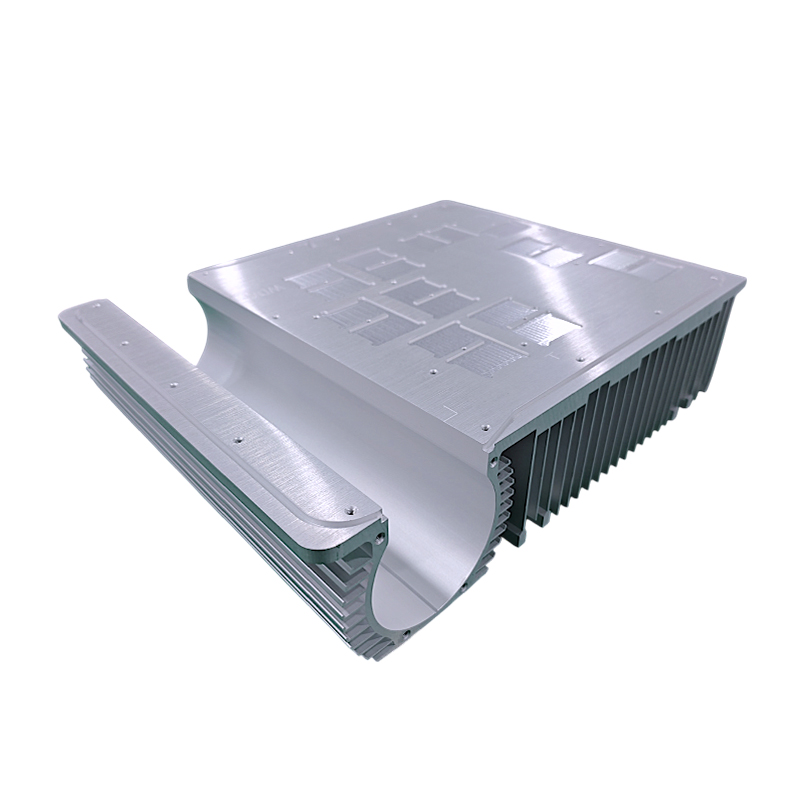
Subtractive manufacturing uses 3-axis to 5-axis milling centers to carve the heat sink from a solid block of billet aluminum or copper. A cnc machined heat sink offers unrestricted geometry, the tightest possible tolerances, and zero tooling costs. It is the go-to method for liquid cold plates, complex internal flow paths, and rapid prototyping.
The primary drawback is cost at volume. Machining generates high material waste and requires extended machine cycle times. Removing large volumes of metal to create deep, narrow fin channels requires specialized tooling and careful programming to avoid tool deflection and chatter. While perfect for low-volume aerospace or defense applications, CNC machining is rarely viable for mass-market consumer electronics unless used strictly for secondary finishing operations on extruded or cast parts.
Forging compresses metal into a die under high pressure, while die casting injects molten metal into a steel mold. Both methods produce complex 3D geometries and near-net shapes that require minimal secondary machining. They are excellent for creating omnidirectional pin fin arrays used in LED cooling and automotive electronics. Cold forging produces highly dense, structurally sound parts with excellent thermal properties.
Forging maintains the high thermal conductivity of wrought aluminum. Die casting, however, relies on specific casting alloys containing silicon to improve flow during injection. These cast alloys inherently suffer from lower thermal conductivity and internal porosity. Both processes demand high initial tooling costs, making them suitable only for high-volume production runs where the tooling investment can be amortized over thousands of units. Draft angles must be incorporated into the design to allow the part to eject from the mold.
This process involves stamping thin sheet metal—usually aluminum or copper—and folding it into dense, corrugated fin arrays. These folded fins are then soldered, brazed, or epoxied to a separate base plate. This method maximizes surface area for forced convection in highly weight-constrained environments, such as enterprise servers and telecommunications equipment.
The major limitation lies in the assembly process. Bonding the fins to the base introduces a secondary interface. If the brazing or soldering process is not perfectly controlled, voids in the joint will create severe thermal bottlenecks. The base plate must also be machined perfectly flat to ensure uniform contact with the folded fin array. Vacuum brazing provides the highest quality joints but significantly increases manufacturing costs.
| Manufacturing Process | Best Application | Tooling Cost | Fin Aspect Ratio Limit | Thermal Conductivity |
|---|---|---|---|---|
| Aluminum Extrusion | High volume, linear airflow | Low to Medium | Up to 20:1 | High (Wrought Alloy) |
| Skived Fin | High density, forced convection | None to Low | Up to 50:1 | High (Billet/Extruded Base) |
| CNC Machining | Complex geometry, cold plates | None | Tooling dependent | High (Billet Alloy) |
| Die Casting | High volume, complex 3D shapes | High | Draft angle required | Low to Medium (Cast Alloy) |
| Folded Fin | Weight-constrained, high surface area | Medium | Extremely High | Dependent on joint quality |
Material properties dictate how fast heat spreads across the base and how efficiently it travels up the fins. Engineers must balance raw thermal conductivity against weight, machinability, and raw material costs. Specifying the wrong alloy leads to manufacturing defects and compromised thermal performance.
Engineers frequently specify an aluminum heat sink for its excellent balance of weight, cost, and thermal performance. However, selecting "aluminum" is not specific enough. The exact alloy series and temper state drastically alter manufacturing outcomes. You must detail the trade-offs on your engineering drawings to ensure the factory uses the correct billet.
Alloy 6063 is the undisputed standard for extruded profiles. It offers superior extrudability, allowing the metal to flow smoothly through intricate steel dies without tearing. It also boasts a thermal conductivity of approximately 200 W/m-K. Alloy 6061 provides higher yield strength and significantly better machinability. It produces shorter chips during milling, preventing tool entanglement. You will typically specify 6061 for a custom heat sink that requires extensive CNC milling or structural threading. However, 6061 has a slightly lower thermal conductivity of roughly 167 W/m-K. Temper states, such as T5 or T6, dictate the final hardness and must be specified based on structural requirements.
Copper (C11000) delivers a massive thermal conductivity of nearly 390 W/m-K. It spreads heat twice as fast as aluminum. Analyze exactly when to specify copper, as it carries severe cost and weight penalties. Copper is three times heavier than aluminum and significantly harder to machine. Use solid copper only for extreme heat flux densities where aluminum physically fails to spread the heat away from a small silicon die fast enough to prevent thermal throttling.
For most high-power applications, evaluate hybrid approaches instead. Embed copper heat pipes or vapor chambers directly into an aluminum base. The phase-change mechanics inside the vapor chamber spread the heat instantly across the entire footprint. The aluminum fins then dissipate that heat into the air. This hybrid approach delivers the thermal spreading performance of solid copper at a fraction of the total weight. Ensure the factory has the capability to solder or epoxy these heat pipes into the base with minimal voiding.
| Material Grade | Thermal Conductivity (W/m-K) | Density (g/cm³) | Primary Manufacturing Method |
|---|---|---|---|
| Aluminum 6063-T5 | 200 | 2.70 | Extrusion |
| Aluminum 6061-T6 | 167 | 2.70 | CNC Machining |
| Copper C11000 | 388 | 8.89 | Skiving, Machining, Forging |
| Die Cast A380 | 109 | 2.76 | Die Casting |
A brilliant thermal design fails instantly if the manufacturing partner cannot hold tolerances or control their supply chain. Vetting a vendor requires looking past their marketing materials and auditing their actual engineering capabilities. You need a partner who understands thermal dynamics, not just metal cutting.
Verify mandatory quality systems before sharing CAD files. Look for ISO 9001:2015 for baseline manufacturing control. Require AS9100D for aerospace and defense projects to ensure strict traceability of raw materials. Demand IATF 16949 for automotive applications to guarantee rigorous statistical process control and PPAP documentation. Confirm RoHS and REACH compliance for all materials. This applies not just to the base metal, but to all surface finishes, plating chemicals, and applied Thermal Interface Materials (TIMs).
Assess the vendor's ability to provide true end-to-end services. They should offer rigorous Design for Manufacturability (DFM) feedback during the quoting phase. They must handle tooling creation, extrusion, and mass production internally. Evaluate their secondary operation capabilities closely. Look for in-house CNC finishing centers, precision flatness grinding machines, and automated TIM dispensing systems. Ask for equipment lists and verify their metrology lab capabilities, including CMMs and optical comparators.
Fragmented supply chains increase lead times and quality risks. If a vendor extrudes the profile but subcontracts the CNC machining and anodizing to third parties, accountability vanishes when a batch fails inspection. Single-source manufacturing ensures tight control over dimensional tolerances from the raw billet to the final packaged part. It also protects your intellectual property from being distributed across multiple unvetted machine shops.
Evaluate the vendor's Minimum Order Quantity (MOQ) flexibility early in the discussion. Determine if they can support low-volume niche runs for specialized development boards or pilot builds. Verify they can seamlessly scale to high-volume production. This scaling must happen without requiring a change in the manufacturing facility or the underlying process. Transitioning from a prototype shop to a separate mass-production facility introduces massive risk regarding tool paths, fixture design, and quality control standards.
Thermal management hardware sits at the end of the mechanical design cycle. Mistakes here delay entire product launches. Anticipating manufacturing risks prevents costly late-stage redesigns and ensures the final product meets all thermal specifications under real-world operating conditions.
The most common engineering failure involves the prototype-to-production gap. The risk occurs when you validate a thermal model using a CNC machined prototype, then switch to die-casting for mass production to save money. This results in unexpected and severe thermal degradation. Billet aluminum used for machining has vastly different thermal properties than silicon-heavy cast aluminum. Your production units will run significantly hotter than your prototypes, potentially causing field failures.
Mitigation requires strict discipline. Prototype using the intended production process whenever possible. If you must machine a prototype for a part intended for casting, apply strict derating factors to your CFD models. Artificially lower the thermal conductivity in your simulation software to match the cast alloy. This accounts for production variations, porosity, and lower material performance. Always run a First Article Inspection (FAI) on the initial production run to verify thermal performance matches the prototype data.
The interface between the component and the heat sink is the largest bottleneck in any thermal system. The risk involves poor base flatness or excessive surface roughness. A warped base increases the bond line thickness of the TIM. Because TIMs have relatively low thermal conductivity compared to metal, a thick TIM layer acts as an insulator, severely degrading overall cooling efficiency. Thermal cycling can also cause TIM pump-out if the base is not perfectly flat.
Mitigation requires aggressive tolerance control. Specify strict flatness tolerances on the manufacturing drawing, typically calling out 0.001 inches per inch or better. Require precision fly-cutting, lapping, or grinding as a secondary operation for the mounting surface. Control the surface roughness (Ra) to ensure it is smooth enough to minimize air gaps, but textured enough to hold the thermal grease in place during thermal cycling. Specify the exact TIM application method, such as screen printing, to guarantee a uniform bond line thickness across the entire production run.
Define maximum allowable thermal resistance and pressure drop limits before evaluating any manufacturing method.
Match required fin density and geometry directly to the most cost-effective fabrication process capable of meeting those specifications.
Request DFM feedback from the manufacturing partner immediately after the initial CAD draft to avoid designing un-manufacturable features.
Specify exact alloy grades, temper states, and surface finishes on engineering drawings to prevent unauthorized material substitutions.
Prototype using the exact manufacturing process planned for mass production to validate CFD thermal models accurately.
A: Aluminum extrusion is generally the most cost-effective method for high-volume production. It features low tooling costs and rapid production cycles. However, it is strictly limited to linear fin geometries and moderate aspect ratios, making it unsuitable for extreme-density applications.
A: Skived fins allow for much higher fin densities and significantly thinner fin profiles than extrusion. Because the fins are carved directly from the base material, there is zero thermal interface resistance between the base and the fins, maximizing heat transfer efficiency.
A: Specify CNC machining when your design requires complex, non-linear geometries, integrated liquid cooling channels, or extremely tight dimensional tolerances. It is also the ideal choice for rapid prototyping and low-volume production runs where expensive tooling costs cannot be justified.
A: High surface roughness on the heat sink base creates microscopic air gaps between the heat sink and the heat-generating component. Air is a poor conductor. Overcoming these gaps requires a thicker layer of Thermal Interface Material (TIM), which increases thermal resistance and degrades cooling efficiency.
A: Yes. Hybrid heat sinks frequently use a solid copper base or embedded copper heat pipes to rapidly spread heat away from a small, high-power component. The heat is then transferred to aluminum fins, which dissipate it into the air while keeping the overall assembly lightweight.


