- All
- Product Name
- Product Keyword
- Product Model
- Product Summary
- Product Description
- Multi Field Search


Views: 0 Author: Site Editor Publish Time: 2025-06-09 Origin: Site


The energy equipment industry is rapidly transforming as renewable sources (solar, wind) integrate into the grid, microgrids proliferate, and smart‐grid architectures advance. Conductive strips—often called busbars—play a central role in carrying current between inverters, batteries, and control panels. Today's systems demand busbars with flexible dimensions and mounting features to fit irregular enclosures, conserve space, and simplify maintenance. Precision manufacturing combined with innovative structural design delivers customized busbar solutions that enhance integration, reduce downtime, and ensure reliable performance in diverse environments.
Conductive strips can take many shapes—flat bars, U‐channels, L‐brackets, T‐sections, or even composite laminates. Choosing the right profile hinges on three factors: electrical capacity, thermal management, and mechanical robustness.
Flat Busbars: A 50 mm × 5 mm copper strip can carry hundreds of amps with minimal resistive loss. Its broad, shallow surface helps dissipate heat naturally. However, flat bars may sag or vibrate if not properly supported.
U, L, and T Profiles: A U‐shaped busbar (e.g., 40 mm × 5 mm with 10 mm flanges) slips over a mounting channel, saving vertical space. L‐shaped sections combine current‐carrying capacity with built‐in heat‐sink flanges, guiding air over the hot surfaces. T‐profiles can align three phase conductors in a compact arrangement while preserving clearances. These shapes resist bending and vibration better than flat strips in cramped cabinets.
Composite and Multi‐Layer Designs: When one layer cannot carry the required current, multiple copper or aluminum layers—separated by thin insulating film—are stacked. This “busbar sandwich” increases cross‐section without widening the footprint. A graphite‐filled silicone layer between copper sheets also boosts thermal spreading, ideal for systems that exceed 1,000 A continuously, such as large battery energy storage systems (ESS).
By selecting the appropriate cross‐section—flat for moderate currents in open racks, U‐ or L‐profiles for compact enclosures, or layered composites for extreme loads—engineers meet specific current and space requirements while maintaining safe operating temperatures.
Downtime is costly. To support rapid service or upgrades, custom busbar segments often incorporate hot‐swap, plug‐in features:
Segmented, Removable Busbars: Rather than one continuous strip, the busbar divides into modules—each carrying a single phase or functional zone (e.g., inverter output, battery input). A quick‐release latch or cam lock ensures solid contact and enables removal in under two minutes. Technicians can isolate and replace a segment without disabling the entire system.
Standardized Terminal Blocks and Connectors: By using universal connector footprints, a faulty terminal block can be swapped with any compatible brand’s block. Color‐coded insulating housings and mechanical keys prevent miswiring. Alphanumeric labels on each connector correspond to wiring diagrams, accelerating field identification.
For instance, in a distributed ESS rack, a technician can remove one battery module’s busbar segment in 10 minutes, perform maintenance, and restore service without disrupting neighboring modules—crucial for 24/7 operation.

High‐current busbars inevitably heat up. Custom solutions incorporate thermal strategies to prevent hotspots and prolong busbar life:
Thermally Conductive Interface Materials: In areas where lugs clamp to the busbar, a thin graphite‐reinforced silicone pad fills micro‐gaps, minimizing contact resistance and routing heat into a larger heat sink or chassis.
Integrated Heat Sink Fins: Busbars may feature stamped or machined fin arrays. In power converter cabinets, these fins bolt or solder to the busbar, and fans blow air across them, keeping temperatures in check.
Aluminum Backplate Bonding: An extruded aluminum plate behind the busbar acts as a heat spreader. A thin insulating pad ensures electrical isolation while allowing thermal conduction. This is common in rooftop PV inverters, where ambient temperatures reach 45 °C.
Cooling approaches include:
Natural Convection: Vertical busbar arrangements with 50–100 mm clearance above and below let warm air rise and exit through top vents, drawing cooler air in from below—suitable for medium‐power (100–500 A) systems.
Forced Air Cooling: When currents exceed 500 A, fans or blowers create directed airflow through finned busbars. Baffle plates channel air over critical hot zones, preventing uneven heating.
On‐Demand Cooling: Temperature sensors trigger fans only when load surpasses 80% or ambient exceeds 35 °C, reducing fan power consumption and extending fan life.
Well‐engineered thermal management ensures busbar temperatures stay below 75 °C–85 °C, safeguarding insulation, coatings, and adjacent components.
Custom busbars must meet stringent safety standards to prevent arc flash, electric shock, and mechanical hazards:
Insulation and Creepage Distances: For voltages up to 1 kV, designers maintain minimum creepage distances of 5–8 mm (per pollution degree 3). Insulating barriers or troughs separate phases and isolate busbars from grounded chassis.
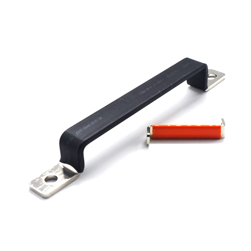
Insulating Sleeves and Epoxy Coatings: Exposed edges and bends receive molded PVC or silicone sleeves (UL 94 V0 rated). In tight spaces, a thin epoxy conformal coat (0.2 mm) protects against accidental contact and prevents corrosion without trapping excessive heat.
Protective Shields and Warning Labels: Clear polycarbonate barriers (10 kV dielectric) guard high‐voltage busbars, allowing visual inspection while preventing accidental contact. ANSI Z535‐compliant yellow‐black stripes on covers and doors warn of hazardous voltage.
Lockout/Tagout (LOTO) Points: Integrated LOTO holes let technicians padlock busbar segments, preventing unintended re‐energization during maintenance.
Anti‐Vibration Fasteners: Belleville (conical) spring washers, nylon‐insert lock nuts, or riveted standoffs keep busbars secure under continuous vibration (e.g., offshore wind turbines, rail traction inverters). For severe vibration, busbars may be spot‐welded to standoffs in addition to bolting. Anti‐twist insulating brackets grip busbar flanges, preventing lateral movement.
Combining these safety features ensures busbar assemblies comply with IEC 61439 (low‐voltage switchgear), UL 857 (power distribution equipment), and other regional standards, while protecting personnel and equipment.
A utility company commissioned a 5 MW/20 MWh distributed ESS comprising multiple cabinets. Each cabinet’s busbar divided into four 250 A segments—two for charging, two for discharging. To minimize downtime during maintenance, tailored busbar modules included:
Plug‐In Segmented Busbars: Each 250 A segment used a cam‐lock lever that pressed copper strips onto gold‐plated contact pads. Removing the lever released the segment instantly.
Standardized Terminal Inserts: Recessed connector housings allowed any replacement segment to plug into the same footprint.
Integrated Thermal Pads: Thin graphite pads between busbar and aluminum backplate ensured even heat spread.
Quick‐Release Latches and Safety Interlocks: Removing a segment automatically opened a plastic shroud, exposing no live conductors
During a field test, a defective segment was identified by elevated temperature readings. A technician placed the cabinet in maintenance mode, locked out the faulty segment via the LOTO hole, then released the cam‐lock lever. In under ten minutes, the segment was swapped with a spare and tested—without shutting down adjacent cabinets. The utility reported zero interruption to grid support services.

As renewable integration, microgrid deployments, and smart‐grid rollouts accelerate, customizable busbar solutions become indispensable. Precision manufacturing enables busbars that:
Fit Unique Layouts: By selecting flat, U, L, T, or composite cross‐sections, engineers meet varying space and current demands.
Simplify Maintenance: Modular segments and standard connector interfaces let service personnel swap parts in minutes, reducing downtime.
Manage Heat Effectively: Conductive pads, integrated heat sinks, and optimized airflow maintain safe operating temperatures.
Ensure Safety: Adequate spacing, insulating sleeves, clear shields, and vibration‐proof fasteners protect both equipment and personnel.
Shenzhen Wandaan Precision Technology Co., Ltd. offers comprehensive expertise in custom conductive strip design:
Structural Design: Full 3D CAD modeling and FEA validation ensure each busbar geometry meets electrical, mechanical, and thermal requirements.
Precision Machining: CNC centers and automated bending lines produce busbars to ±0.02 mm tolerances, with quick‐change tooling for rapid turnaround.
Assembly Validation: In‐line inspection verifies dimensions and surface finishes; thermal imaging validates cooling performance before shipment.
For optimal results, engage with Wandaan's engineering team early—using 3D simulations and thermal analyses to finalize busbar layouts and mounting strategies. By leveraging Wagdan's “design + precision processing + validation” approach, energy equipment OEMs and EPC contractors can deploy tailored busbar systems that maximize reliability, simplify maintenance, and reduce total cost of ownership.
Choose Wandaan to bring precision, flexibility, and rapid responsiveness to your next renewable or smart‐grid project.